(Traditionally, the bits in registers are numbered right to left, starting with 1.)
|
41 |
|
||||
| Exponent | Sign (pos=0, neg=1) | Mantissa (2-complement) |
| 6 |
|
2 | 1 | ||
| Suppress FPE | ω (omega) mode | Suppress rounding | Suppress normalisation |
ω mode could have the following values:
All instructions are 24 bit wide and are packed into words in pairs. The branches can be made to word boundaries only.
There are two formats:
| Format 1 | ||||||||||
|---|---|---|---|---|---|---|---|---|---|---|
|
20 | 19 |
|
|
||||||
| M | 0 | S | OPCode1 | offset | ||||||
| Format 2 | |||||||||
|---|---|---|---|---|---|---|---|---|---|
|
20 |
|
|
||||||
| M | 1 | OPCode2 | offset | ||||||
Traditionally, the opcodes in opcode lists are written in octal including bits 20 to 13 or 20 to 16 and assuming S = 0, therefore the opcode ranges are 000 to 077 for format 1 and 20 to 37 for format 2.
The following mnemonics are used in descriptions:
The opcode descriptions are too brief to be exact. The behavior of most arithmetic instructions depends on normalisation and rounding mode, and the behavior of branch instructions depends on the value of the ω mode. For instructions setting additive or multiplicative ω mode, A and X are considered floating point (unless said otherwise), for logical instructions - unsigned integers.
More precise descriptions will follow.
The way register Y is used, although seems bizarre at first, is to simplify the implementation of double precision arithmetic (the second word of a double precision value holds LSBs of mantissa and MSBs of exponent).
| Opcode | Mnemonic | Description | Formula | ω mode |
|---|---|---|---|---|
| 000 | ATX | Store | X = A; | Kept |
| 001 | STX | Pop | X = A; A = mem[--M[017]]; | Logical |
| 002 | MOD | Modify privileged registers (kernel) | Log/Kept | |
| 003 | XTS | Push | mem[M[017]++] = A; A = X; | Logical |
| 004 | A+X | Add | [A,Z] = A + X; | Additive |
| 005 | A-X | Subtract | [A,Z] = A - X; | Additive |
| 006 | X-A | Reverse subtract | [A,Z] = X - A; | Additive |
| 007 | AMX | Subtract absolute values | [A,Z] = abs(A) - abs(X); | Additive |
| 010 | XTA | Load | A = X; | Logical |
| 011 | AAX | Bitwise AND | A = A & X; Y = 0; | Logical |
| 012 | AEX | Bitwise Exclusive OR | Y = A; A = Y ^ X; | Logical |
| 013 | ARX | Cyclical add | (unsigned) A += (unsigned)X; if (carry) (unsigned)A++; Y = 0; | Multipl. |
| 014 | AVX | Negate | if (X < 0) A = -A; Y = 0; | Additive |
| 015 | AOX | Bitwise OR | A = A | X; Y = 0; | Logical |
| 016 | A/X | Divide | A = A / X; Y undefined; | Multipl. |
| 017 | A*X | Multiply | [A,Z] = A * X; | Multipl. |
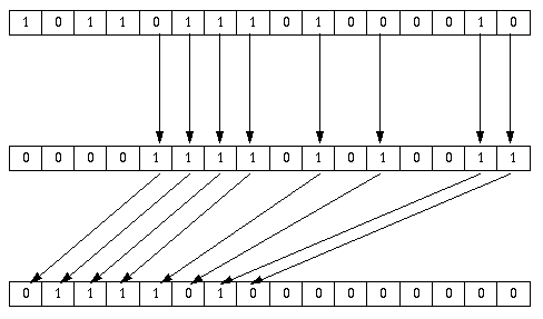
| 020 | APX | Pack bits in A masked by X. Did the inventors of INTERCAL know about this instruction? | Logical | |
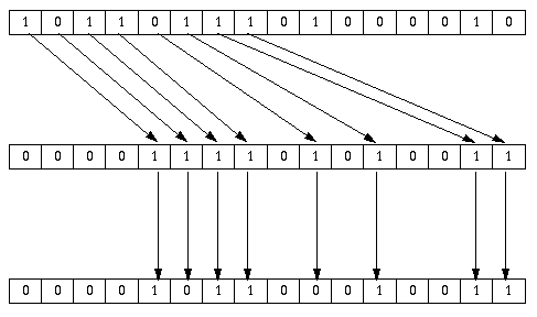
| 021 | AUX | Unpack bits in A using mask X | Logical | |
| 022 | ACX | Population count | A = popcount(A) + X; Y = 0; | Logical |
| 023 | ANX | Find highest set bit | A = high_1_and_rest(A) + X | Logical |
| 024 | E+X | Add exponent | E += X[48:42] - 64; Y = 0; | Multipl. |
| 025 | E-X | Subtract exponent | E -= X[48:42] - 64; Y = 0; | Multipl. |
| 026 | ASX | Shift | Y = 0; if (X[48:42] >= 64) [A,Y] >>= X[48:42]-64; else [Y,A] <<= 64-X[48:42]; | Logical |
| 027 | XTR | Set mode register | R = X[47:42]; | As set |
| 030 | RTE | Get mode register | E = R; | Used |
| 031 | YTA | Get young bits register | A = yta (Y, ω mode); | Used |
| 032 | EXT | Access external I/O registers (kernel) | Kept | |
| 033 | --- | |||
| 034 | E+N | Add exponent immediate | E += N - 64; Y = 0; | Multipl. |
| 035 | E-N | Subtract exponent immediate | E -= N - 64; Y = 0; | Multipl. |
| 036 | ASN | Shift immediate | Y = 0; if (N >= 64) [A,Y] >>= N-64; else [Y,A] <<= 64-N; | Logical |
| 037 | NTR | Set mode register immediate | R = N[6:1]; | As set |
| 040 | ATI | Set index register | I = A[15:1]; | Kept |
| 041 | STI | Pop into index register | I = A[15:1], A = mem[--M[017]]; | Logical |
| 042 | ITA | Get index register | A = I; | Logical |
| 043 | ITS | Push index register | mem[M[017]++] = A, A = I; | Logical |
| 044 | MTJ | Move index register | J = M; | Kept |
| 045 | J+M | Add index registers | J += M; | Kept |
| 046 | Unused, but identical to 044 and 045, respectively | |||
| 047 | ||||
| 050 . . . 077 | *nn | Extra-codes, used as system calls and math library functions | Varies or undefined | |
| 20 | ||||
| 21 | ||||
| 22 | UTC | Set C register immediate | C = U; ("UTC 0" == NOP) | Kept |
| 23 | WTC | Set C register | C = X[15:1]; | |
| 24 | VTM | Set index register immediate | M = V; | |
| 25 | UTM | Add to index register immediate | M += V; (or M = U;) | |
| 26 | UZA | Branch if ω == 0 | Y = A; if (omega() == 0) K = U; | Used |
| 27 | U1A | Branch if ω != 0 | Y = A; if (omega() != 0) K = U; | |
| 30 | UJ | Unconditional branch | K = U; | Kept |
| 31 | VJM | Jump to subroutine | M = K + 1; K = V; | |
| 32 | IJ | Return from interrupt (kernel) | ||
| 33 | STOP | Stop (unprivileged :-) ) | ||
| 34 | VZM | Branch if index is zero | if (M == 0) K = V; | |
| 35 | V1M | Branch is index is not zero | if (M != 0) K = V; | |
| 36 | Unused, but identical to 34 | |||
| 37 | VLM | Loop | if (M != 0) { M++; K = V; } | Kept |
All instructions except UTC and WTC reset C to 0 after execution.
If V of the current instruction is equal to 0 and the index register being used is 017, the following instructions are executed in stack mode:
(It is left to the reader to figure out the semantics
of STX [017] and XTS [017].)
high_1_and_rest(word48 a) {
    int bit = 1;
    if (a == 0) {
	Y = 0;
	return 0;
    }
    while (!(a & 0x800000000000)) {
	bit++;
	a <<= 1;
    }
    Y = a << 1; /* the rest of A */
    return bit;
}
The original instruction set manual assumes a slightly simpler algorithm and says that A = 1 and A = 0 yield the same value 48, "which is somewhat unfortunate"; but in fact all the machines made (even the first one) had the instruction implemented the "correct" way.
| A |
 |
|---|---|
| X | |
| Result |
| A |
 |
|---|---|
| X | |
| Result |
For the UZA and U1A instructions, the ω condition is calculated as follows:
switch (ω mode) {
	case additive: ω = (A[41] != 0); /* A < 0 */ break;
	case multiplicative: ω = (A[48] != 1); /* abs(A) < 0.5 */ break;
	case logical: ω = (A[48:1] != 0); /* A != 0 */ break;
	case 0: ω = 1;
}
If the current ω mode is "logical", then A = Y; else A[40:1] = Z, A[41] = 0, E += N - 64;
The BESM-6 pages have been accessed 1196 times.